You are using an out of date browser. It may not display this or other websites correctly.
You should upgrade or use an alternative browser.
You should upgrade or use an alternative browser.
Im stuck
- Thread starter youngnick
- Start date

Emery19
New member
slam on it with a hammer or something to shock it free. thats what we did on our plow truck and on my car. the plow truck was a little more stubborn then the car, had to break out the sledge.
B.Warning
New member
Hard to tell, but do you have the 'C' clip out?
If so grab a dead blow hammer and start hitting it from the back side. It'll come.
If so grab a dead blow hammer and start hitting it from the back side. It'll come.
taterthedog
Active member
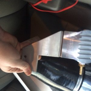
Take lock out of slot in spindle ( 10 o'clock in your pic), then unscrew big hub nut. Then the bearings and rotor should slide off.
Sent from my iPhone using Tapatalk
Sent from my iPhone using Tapatalk
taterthedog
Active member
The little lock goes between the spindle and the nut to keep the nut from backing off. The spindle is stationary with threads on the outside and the axle shaft inside it. There are several different styles of spindle nuts, that one looks to be the kind that takes a big thin walled socket. You should be able to spin it off by hand after starting it with a screwdriver or something. If you get a rag and wipe away some grease it should look clearer, I'm only looking at it on my phone. When reassembling make sure the bearing is packed with grease and properly torque the spindle nut. You don't want to over tighten it.
Sent from my iPhone using Tapatalk
Sent from my iPhone using Tapatalk
taterthedog
Active member
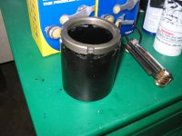
Quick google search to help me explain.
Spindle nut

Socket

Just to give you an idea what you are working with.
Sent from my iPhone using Tapatalk
Spindle nut
Socket
Just to give you an idea what you are working with.
Sent from my iPhone using Tapatalk
Isobaric
New member
- Joined
- Nov 20, 2014
- Messages
- 68
- Reaction score
- 0
I keep reading that but i have only one notch in mine and its completely round so how do i get either one on and take that nut off? Better yet how do i put it back on and torque it down?
Sent from my SAMSUNG-SGH-I537 using Tapatalk
Sent from my SAMSUNG-SGH-I537 using Tapatalk
taterthedog
Active member
You need a spindle socket like I posted. The hex part for the socket is on the inside flange. Isobaric posted a different kind of spindle nut and socket. Some trucks have that type but according to your picture you have the type I posted. Let us know how you make out.
Sent from my iPhone using Tapatalk
Sent from my iPhone using Tapatalk
What are the specs on tourqing it I ran to the same boat and my Manuel does not show it
You need the correct socket for the nut, and follow the procedure. It should be in a service manual like Haynes or Chilton. If I recall correctly, you pull in down right to a certain torque value, then back it off a half turn. I usually go by "feel" and spin the hub with the wheel on it when I am setting the bearings in. It also makes a difference if you are using the old bearings or new ones.
To get the rotor off the hub you need to take the whole hub off and lay it on the ground. Take a block of wood and lay it over the hub. Then proceed to dive the hub downward with a large sledge until you get it to move. I suppose you could use a press if you have one available. They can be very difficult to get apart. I spray plenty of PB Blaster around the lug holes and hub when I'm working on them.
Patrick Feeley
Member
From the service manual (depending on what hubs you have):
Front Wheel Bearing
Automatic Locking Hubs
1. Raise the vehicle and install safety stands.
2. Remove the hublock assembly. Refer to «Automatic Locking Hub» removal and installation in this section.
3. Remove retaining lock ring or C-ring and three-piece thrust washers. Remove cam assembly and wheel nut retaining key (if not already removed).
4. Loosen wheel bearing retainer (nut) using Hub Nut Wrench T95T-1197-A for F-150 and Bronco or T95T-1197-B for F-250 and F-350 with automatic locking hubs. While rotating rotor and hub, retighten wheel bearing retainer (nut) to 68 N-m (50 lb-ft) to seat wheel bearings.
5. Back off nut 90 degrees (1/4 turn). Tighten wheel retainer nut to 1.8 N-m (16 lb-in). If necessary, tighten nut to next slot to allow installation of retainer key.
6. Install retaining key into the spindle keyway by inserting the short leg into the aligned slot in nut. Press all the way into position until curved portion of retaining key is seated into counterbore of wheel retainer (nut).
7. Install cam assembly.
8. CAUTION: Improper sequence of three-piece thrust washers will result in excessive wear of assembly.
Install three washers in order: metal washer first, plastic washer second and splined washer last.
9. Install C-ring or lock ring. Align legs of cam assembly for installation of hub body.
10. Check that the final end play of the front disc brake hub and rotor on the front wheel spindle is 0.00-0.50mm (0.000-0.002 inch).
11. CAUTION: Excessive end play or torque greater than 2.3 N-m (20 lb-in) to rotate hub and rotor will result in excessive wear of wheel bearings.
Torque required to rotate the front disc brake hub and rotor is not to exceed 2.3 N-m (20 lb-in).
12. Install hublock. Tighten screws to 4-6 N-m (35-53 lb-in).
13. Remove safety stands. Lower vehicle.
Manual Locking Hubs
1. Raise the vehicle and install safety stands. Remove caliper and brake pads. Refer to «Section 06-03».
2. Remove the hublock assembly. Refer to the «Manual Locking Hub» removal and installation procedures in this section.
3. Remove C-ring and three-piece thrust washers (if not already removed).
4. Remove the outer lock nut with Hub Lock Nut Wrench T83T-1197-B for F-150 and Bronco or Spanner Locknut Wrench D85T-1197-A or equivalent for F-250 and F-350. Remove the lockwasher and loosen inner lock nut.
5. Using spanner lock nut wrench while rotating the front disc brake hub and rotor (1102) back and forth, tighten the inner lock nut to 68 N-m (50 lb-ft) to seat the bearing.
6. Back off the lock nut 90 degrees.
7. Note: Hole pattern of lockwasher is offset with keyway to provide half-position settings by flipping washer over to obtain closest hole.
Install the lockwasher so the key is positioned in the groove of the front wheel spindle (3105). Tighten the inner lock nut, aligning the pin into the nearest lockwasher hole.
8. Install the outer lock nut and tighten to 217-278 N-m (160-205 lb-ft) using Hub Locknut Wrench T83T-1197-B for F-150 and Bronco or Spanner Locknut Wrench D85T-1197-A or equivalent for F-250 and F-350.
9. Check the final end play of the front wheel spindle. It should be 0.00-0.05mm (0.000-0.002 inch).
10. Torque required to rotate the front disc brake hub and rotor is not to exceed 2.3 N-m (20 lb-in).
11. CAUTION: Improper sequence of three-piece thrust washers will result in excessive wear of assembly.
Install three washers in order: metal washer first, plastic washer second and splined metal washer third. Install C-ring.
12. Install the hublocks. Refer to «Locking Hubs» in the Removal and Installation portion of this section.
13. Remove the safety stands. Lower the vehicle.
Hope that helps! Cheers!
Super great!! My manual didnt have it
Yeah, you owe him a beer.
Thanks for that info. got that part off. but now im really stuck. im trying to do ball joints and i cant get the spindle off. i unbolted it and even knocked out the studs. i have beat the crap out of it that im worried about destroying it. am i correct on taking off the spindle? and how do you separate the knuckle?
im gonna search the info web but any help with the dana 50 please go ahead
thanks
im gonna search the info web but any help with the dana 50 please go ahead
thanks