lincolnlocker
Well-known member
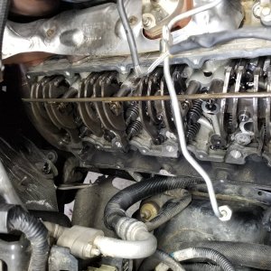
double check hpo rail fittings and ebpv actuator rod. the orings around the rod are knkw for leaking
live life full throttle
live life full throttle

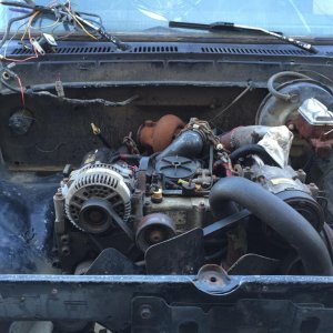
whs^^^ spot on.. and while its running please for the love of god dont forget about the fan spinning!!!!Is that you motor or just a pic you snagged. I like the fuel feed lines on that motor.
If there is oil in the valley, you have to clean it all out, if you wash it out it will drain out that hole it the back passenger side of the valley. That oil can be coming from the HPOP, the pedestal, the HPO rails or the HPO lines. You have to clean it, run it and observe with a light while it is running to find the leak.
Reading through this i had to think about how to post a reply. This is long winded so I apologize.
Using this forum is great, a lot of experience and knowledge.
You stated (originally) several things regarding gp's, starting and irregular idle and rev issues.
New batteries, new starter and I believe a start relay. I believe you stated a cable started "smoking". ALL of these issues can be attributed to bad cables. This increases amperage draw which can toast ALL of those components.
EXTREMELY critical are the ground circuits. Bad grounds can cause erratic signals to the pcm, most precisely it can (and does cause erratic/intermittent) issues with the DC sine wave generated by the cps.
It was stated that you didn't want to just throw $$$$ at it however I saw where you where going to replace all the sensors, why? Now if you find obvious issues, oil soaked icp, well then replace it. Many people have stated this is an indication of a bad sensor, they know from experience.
One thing that has to be understood is that the pcm is a computer. No different than any pc in that it requires inputs and based upon those the programming, written code, is based on those inputs. You can change all sorts of things simply by using potentiometers or resistors to "fool" the pcm into doing something. There are mins/maxs on sensors before codes are set and many work together.
With that being said the sensors have a voltage reference(5vdc), ground and a signal return. Some sensors use these dedicated 3-wires, others use 2-wires using a ref voltage and signal return and engine ground while others use a single wire sending power to the sensor with an engine ground.
All of these sensors have parameters based on pressure or resistance.. Take the EOT, it drops resistance as the oil temp increases, increasing the voltage signal returned to the pcm. The throttle pedal uses a potentiometer which changes resistance depending on pedal position which in-turn changes the signal return to the pcm.
Don't just change components, sensors and parts. That's what 99% of shops seem to do anymore. I recently traded the use of a shop bay(truck work) for repairing a pos Suzuki Grand Vitara. They had 5 guys trying to fix the dam thing for over a month. The manager was told he was fired monday morning it it was still there. The problem came down to a crankshaft position sensor issue(has crankshaft as well as two camshaft sensors). It was reading one thing while the two others were reading something else. PCM was confused because cams run the injectors while crank fired the coils. I can't tell you how many things they "threw" at it. Again, the pcm has written code based on inputs.
GP's reading 0. They should have a resistance of 1.0-1.2ohms. You MUST have a good meter with a 200ohm scale. If you read 0 how could that be a harness issue? Loose should increase resistance(not always), an open circuit wouldn't read anything. Reading 0 is the same as touching your leads together. The resistance is what causes them to heat when current is passed through them back to the engine ground. No resistance equals bad GP's.
I've gone on for quite a bit but I feel this type of testing is crucial. It has to be done correctly otherwise you are just throwing $$$ at it.
Btw, Hall Effect switches are magnetic pickups. TFI modules in distributors, VSS from rearends/transmissions and our notorious CPS or CAMP. An AC sine wave is created when a "sprocket" type ring is passed by the magnetic pickup/sensor. In the case of the CPS it uses a Darlington amplifier and a Schmitt trigger to convert it to a DC sine wave signal back to the PCM. The test for this is to pull the IDM relay. A voltage of 0.3 to 2.7vdc is generated on the signal return when cranking it over by hand. The 7.3 uses a slightly different gap on the camshaft "ring" before cyl#1 and a different one before cyl#4. The pcm "sees" this difference, wether it speeds up or slows down, to "time".
I believe someone said they might use a "Hall Effect" sensor to read voltage to the GPR. Nope. Use of an "inductance" pickup is needed to read the amperage draw. shunts "isolate or suppress" RFI and EMI. Diodes are simply "one-way" electrical gates.
Sorry about the rant.
I was taught to call or ask either of you, lol!
 . Basically it starts right up every time, has no blowby at startup. Then once it's up to operating temp it gets blowby like in the original video, and very slightly smokes (more like a haze) at idle but then goes away at higher rpms . Driving it seems like it has no boost. It's not like a loss of power, until about 50mph. compared to my work truck (a l99 f350 stock 160k) it seems way more powerful but that thing has seen better days. It will not stop smoking though, if you go wot it will smoke through every gear, any speed, doesn't matter. I've just been leaving the truck alone for the last 2 weeks or so, I know it's not running quite right so there's just no reason to push it and make it worse.