Here ya go from what I posted up on PSN
Ford Super duty Excursion Door Actuator $0 fix
Symptom:
The problem is that when I hit the switch, the locks attempt to move and after repeated attempts, the signal appears to get weaker and weaker until nothing....I assumed relay or switch.....NOT THE CASE!
First I started by testing the signal at the harness plug to the actuator. Perfect. No issues here. Next I completely removed the actuator/lock mechanism and bench tested them with 12V..Here lies the problem. The actuator acted the same as when in the truck. First I did a thorough cleaning of all of the mechanism so it works freely and still had the same results. Here's where it get's tricky. These things are built so that they are NOT serviceable. I had already decided that they were going to need to be replaced, so I decided to break them open for closer inspection. It comes apart relatively easily, but appears that It cannot be put back together once apart. I drilled out two small rivets and then pried the case apart. As you pry the case apart you'll notice these small little plastic rods protrude up through the case cover. These rods are then "mushroomed" with heat through the upper case and then sealed with some kind of silicone. When you pry apart the case the "mushroom" head breaks off and the rod remains. You can dig out the silicone and mushroom head with a pick. It comes out very easy. Inside you will find a very small motor and some gear mechanism. I believed the problem at first to be worn brushes or dirty commutator contacts in the motor itself. You'll have to bend two little metal tabs out and pull off the brush housing on the back of the motor. I cleaned the gunk off the brushes and took 1500 grit to the commutator contacts and reassembled the motor. The motor worked, but if you applied even a slight amount of resistance on the armature, it would stop the motor. It should have been WAY stronger than this. I was stumped until I looked a little closer at the inside of the plastic brush housing. Inside you'll find a small, thin rectangular (thermal resistor relay, dodad, thingamabob??) pardon my ignorance, but I'm not sure what to call it. All I know is that this little part is what keeps you from burning up the motor, should you continue to press the switch once the lock has been actuated. It appears that this thing wears out over time and will not allow enough signal to get through to the motor to make it work. THE FIX. I am cheap. Since I had done so much work up to this point, I decided that I would go a little further and try to make it work without spending the $$. I have better things to spend my money on than actuators. I took a small piece of aluminum foil and wrapped the "thing" voila! Perfectly working motor! I sat there and operated the thing for 10 minutes including one or two times stopping the armature and holding down the switch to see what would happen. The motor builds heat, but not much. Not enough to worry about. Now that I had a good working motor I decided I would try and reassemble the unit. The problem is you cannot glue the unit together as there is a rubber gasket around the perimeter of the case and if you tried to glue the rods into the case, you would not have enough pressure on the two halves of the case to keep the gears in place (these things actually apply a great deal of torque on the case) What I decided to do is completely break off the plastic rods flush with the bottom side of the case and then drill out the bottom case and screw it together. This worked perfectly. You'll need screws that are the same diameter as the holes in the top of the case to keep it from "wandering". Also the screws should not protrude through the back of the unit as some of the mechanism has some pretty close tolerances and a screw sticking through the back would not allow some of the mechanism to work (this can be remedied with a decent set of wire dikes or a hacksaw). I know all of this is hard to picture, but if you do decide to try this fix, you'll see what I am describing here. The locks are back in and working flawlessly.
(Mental note: read all instructions two to three times before attempting so as not to forget a step)
OK how about some visual aides. We all like pictures :toast:
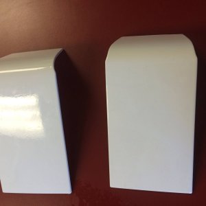
Picture #1
The unit after the two rivets were removed
Picture #2
Prying the unit apart
Picture #3
The open unit minus the motor
Picture #4
Prying the two tabs open on the motor
Picture #5
The opened motor the little metal piece to wrap in tin foil is on the left side of the cap
Picture # 6
Where foil goes and is installed
Picture #7
Now the motor getting ready to be put back together the part is wrapped in foil on the right side in this pic.
How to disassemble the door panel:
-remove inside door panel (2 screws)
-remove door latch screws (3 torx head screws)
-remove outer door handle (2 screws located through inner door) and disconnect the 2 linkages
-remove inside door handle (2 screws)
-drop actuator, disconnect electrical and remove
So more info
Remove the power door lock panel, it just pops off. If it's a front door remove the black panel inside of the mirror above the power door lock panel) Then remove the reflector. There is one screw under the reflector and one under the power door lock panel. remove them and the panel just lifts up and off.
Door lock/latch/actuator are all one unit. It is mounted inside of door with 3 screws.
A couple of thoughts after doing this.
1. I used a drill press to drill off the plastic rivet heads, Just flush with housing. As posted on another post I left the metal rivets intact and pried the housing apart and dropped the motor out, Didn't I really need to see the rest of the actuator.
2. When I replaced the motor I drilled the rivets thru from the previously removed head end using the previous drill center. I drilled these with a #36 bit for a 6-32 thread screw, I then ran a 6-32 tap thru these holes and refastened the actuator housing with 6-32 x 1/2" screws. Note I drilled all six plastic rivet heads but only tapped the four around the motor end. since the metal rivets are still intact on the other end.
3. When I took the motor apart I noticed the relationship between the end bell and the housing. In my case the motor terminals we're opposite the part numbers on the case, You could also make a scratch on the case to retain the orientation of the two parts, I believe this is why some people who have done this have a reverse operation when reinstalled. Rotating the end bell is the same as swapping wires for the change of rotation. Rotating the end bell repositions the brushes on the armature,which changes the polarity.
any way I hope this sheds some additional light on the problem and or solution and again thanks to all who found this
C.T.
Spec. 6-32 screws are the same size as the ones holding your switch and recp. plates on the devices in you house.
Reply With Quote
Update:
I now can repair one in about 15 minutes. I drill the rivets flush with the case, but not the metal ones. I leave them alone. Open the case with a screwdriver blade just enough to remove the motor. Pry open the taps just enough to remove the back case. I do scribe a mark for top on the case and back case so I can install it and get correct operation. I remove the 3/8x1/4 plate resistor which varied on those that don't work from 3 to 5 ohms. Then I solder a 18 gauge copper wire to the end of the plate resistor, with all the insulation removed. Carefully bend the wire around the end of the resistor and solder to the other side. Then install in motor using care not to damage the brushes. Works like a champ. I have also used copper cut to fit which
")
cost me $.01
can't say where the copper came from though. My case is held closed with tiny screws. I drill a 1/16" hole into the plastic rivets and then install the round head screw for a professional looking repair.
Some other tips I saw:
If you don't have to take the actuator all the way off and onto your table... don't. I just did it while the wiring was hanging out through the interior door panel opening. Just remember to use all the holes available to observe what you are doing in the panel, when putting rods/wiring/screws/bolts in place.
I didn't open the metal rivets, but just popped open the plastics ones near the actuator motor. The hardest part for me was getting the small white gear that contacts the actual motor gear in its place. For me it was best to have the black gear, and this white gear (that likes to flop around inside) in place first. Then place the motor in its place with the teeth lined up. Close cover and place a zip tie around the cover near the motor.
More pictures anyone? I love pictures for figuring things out:
ostwhore2:
Picture #8
Start off by taking the (fake) door light cover off with a small flat screwdriver, it pops right off. Then with your hand pull the plastic piece with the window/door lock control up from the front. Now pull out the wiring plugs from the switches.
There will be two screws behind these two parts, using a 9/32 on a 1/4 inch socket wrench with extension remove these two screws. Now lift the entire door panel up about an inch and then out.
Picture #9
Next remove the plastic plug (1) from the door. The nut for the door handle is in here. Then remove the three screws (2) with a T-25 torx bit or driver. This is the door latch that holds the actuator. Next I removed the bolt (3) that hold the bottom half of the window track in place, it is a 10mm. Removing this makes the latch much easier to get out of the door.
Picture #10
Now I remove the door latch, some say they did not but it is easy to do and makes the rods more accessible. You will need a 1/4 inch ratchet with extension and a 7/16 socket. The first nut is straight in from the plastic plug you removed. The other nut is on the opposite corner of the handle and is better accessed with a 7/16 wrench.
Once you have the handle out I release the door handle rod at the bottom toward the latch (2). There is a push clip that holds it in place, just pull on it to release. The door lock (where key goes) rod has a plastic clip also but is a different style (1). It is bent into a U-shape at the end and since I broke one the first time, I now slid it off the "U" by turning the entire (now free from door except this rod) handle around the "U" until it is free.
Picture #11
This pic better shows where to release the rods. 1 is the U-shaped rod for the door lock (key) and 2 is the plastic clip that held the door handle rod in place.
Picture #12
Remove the plastic clip at the latch assembly for the manual door lock rod. I do not have a photo of this but you pull the plastic clip from around the rod and pull the rod out of it's hole, very simple once you see it. Next remove the plastic clips that hold the inside door hand rod in place and the wiring harness for the latch. Just trace these and you will find them, they can be seen easy with the door panel off.
You will need to work the latch Assembly down, this is where removing the 10mm nut from the window track helps as you have more room to work. Once you have it out the hole in the lower part of the door you need to remove the rod holding the inside handle in place. At this point I popped out the rod plastic housing from the latch and used a small pair of pliers to grab the ball at the end of the rod (more like cable) to work the cable free.
Picture #13
Last part is just to remove the two electrical connectors from the latch assembly. Now the latch is free from the door and can be taken apart on your work bench.
This is a very easy fix compared to paying about $175 per door to pay a shop to replace the actuators