Engine fan wiring.

Fordtrucks

New member
Joined
Mar 9, 2013
Messages
503
Reaction score
0
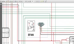
Can anyone give a break down of the wires going in to my fan? There's a plug at the top of the radiator. I'm installing an electric fan kit with a controller. The controller wires directly to the battery but has several probes on it to turn the fans on several different ways. My stock fan is set to kick on at 212° so if I can use that as one probe that would be cool, then a switched 12v from the AC to kick the fans on for that and ide be set. I'll also wire in one of my upfitters so I can manually fire them up if need be.

Is there a couple wires within that factory plug that will provide my 12v signal that I can use? Thanks guys!
 

TD-5

Member
Joined
Sep 12, 2013
Messages
284
Reaction score
2
Location
British Columbia Canada
Not sure if this is any help, its from the wiring diagrams in the 6.4 coffee table PDF;

looking from left to right on the plug:
green = FC-V: fan clutch control from pins #95,96 on the engine harness connector
red= Vpwr: keyed 12 volt power
black= ground
green= FSS: fan speed sensor from pin #90 on the engine harnes connector
RED = VBPWR: 12 volt battery power
 

Attachments

  • E fan connector.jpg
    E fan connector.jpg
    164.9 KB · Views: 103

TD-5

Member
Joined
Sep 12, 2013
Messages
284
Reaction score
2
Location
British Columbia Canada
red= Vpwr: keyed 12 volt power
RED = VBPWR: 12 volt battery power

Sorry, the above is misleading:

Vehicle Power (VPWR)
VPWR is the primary source of PCM power. VPWR is switched through the ECM power relay and is controlled by the ignition switch.

Vehicle Buffered Power (VBPWR)
VBPWR is a regulated voltage supplied by the PCM to vehicle sensors. These sensors require a constant 12 volts for operation and cannot withstand VPWR voltage variations. VBPWR is regulated to VPWR minus 1.5 volts and is also current limited to protect the sensors.
 
Last edited:

Latest posts

Members online

No members online now.
Top