That is just the electronic limit set by the IDM as you can not have signal overlap. That does not mean you have than much crank angle window time to injector the fuel in. Electric vs mechanical limits.
This....

That is just the electronic limit set by the IDM as you can not have signal overlap. That does not mean you have than much crank angle window time to injector the fuel in. Electric vs mechanical limits.
at 3000 rpms if you were running somewhat aggressive timing of say 15 degrees BTDC you have that plus about 24 degrees after TDC for a total of about 40 degrees to make the fuel actually make power (excluding nitrous' magic properties of allowing power to be made even longer after TDC). Take an average injector delay time of about .7ms from the time it is commanded to the time you actually get fuel out of the nozzle and there is the most pulsewidth you can actually do some good with at 3000 rpms.
Doesnt the amount of rotella your.gerotor can ultimately move.come into play at this.point? Or how much can be pushed through the injector rather?
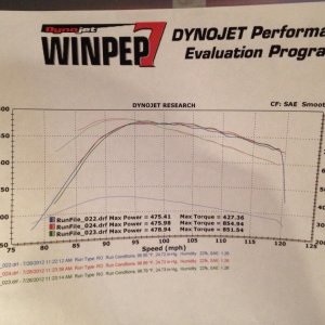
If these inj/nozzle numbers were paper-realistic we'd be making a grand on 300% nozzles by now. Although what Bill did with this is pretty damn good and clean.
That is just the electronic limit set by the IDM as you can not have signal overlap. That does not mean you have than much crank angle window time to injector the fuel in. Electric vs mechanical limits.
at 3000 rpms if you were running somewhat aggressive timing of say 15 degrees BTDC you have that plus about 24 degrees after TDC for a total of about 40 degrees to make the fuel actually make power (excluding nitrous' magic properties of allowing power to be made even longer after TDC). Take an average injector delay time of about .7ms from the time it is commanded to the time you actually get fuel out of the nozzle and there is the most pulsewidth you can actually do some good with at 3000 rpms.
Matt,
That was exactly the post I was looking for.
It is this reason why I and others have said when you look at injector performance for making more power you need rate injectors by what they can do at 2.0 ms and less. We can make power @ 3K its when you get up into 3.5-4K+ we are limited. Also why all the research into finding ways to get the IDM to allow more PW for a standard setup was worthless. It gives you WAY more than you can ever use.
Don't forget refill. That takes time as well, and even firing inside of IDM limits there comes a point where you're not injecting a full shot, as there wasn't enough time to refill a full shot.
But the fact is what the injectors flow on the bench is very close to what they are flowing on the running engine.
We will see very soon.
")
Posted Date:11-23-2008, 02:11 AM
Link to Full Thread on PSN: How the PCM and IDM work http://www.powerstrokenation.com/forums/showthread.php?t=17565
Pretty much every post regarding numbers has put this theoretical maximum at 3.00ms at 4000 RPM. This was validated mathematically by
TXstroker in the following calculations:
4000RPM = 4000/60s = 66.7 (revs per second)
66.7 x 4 = 266.7 injections/sec
1/266.7 = 0.00375 secs = 3.75ms per injection event
3.75 x 0.80 = 3.0ms max PW allowed (using 80% duty cycle rule)
Using the same formula, let's review something similar to what Mustang_GT_350 posted:
RPM------PW ms @ 80% DC
3000------4.000
3250------3.692
3500------3.429
3750------3.200
4000------3.000
4250------2.824
4500------2.667
4750------2.526
5000------2.400
5250------2.286
5500------2.182
5750------2.087
6000------2.000