Troubleshooting CMP: first check the sensor connector for oil - a broken o-ring can cause an oil leak into the electrical connector.
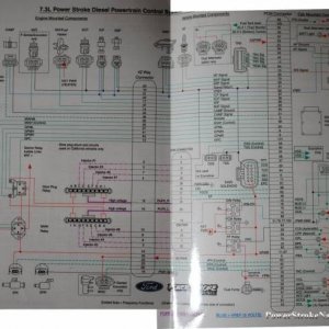
To check the sensor: You can check the red wire (pin 31 ) and the orange wire (at pin 43) at the PCM center connector (C1381c). Using a multimeter that reads hertz check across both wires while cranking, you should see around 1.3 Hz (between 1.1 and 1.9 Hz is acceptable). The operating range of the sensor is 0.5 to 50 Hz.
Testing the sensor AND the wiring: Measure the resistance between the PCM engine connector C1381c (center plug) pin 31, harness side and the same PCM engine connector pin 43, harness side. Should be between 800 and 1000 ohms (sensor AND wiring resistance).
To check the WIRING ONLY: You can measure the resistance between the PCM engine connector (C1381c) pin 31, harness side and the CMP sensor pin 1, harness side; and between the PCM engine connector pin 43, harness side and the CMP sensor pin 2, harness side. Resistance on each test should be less than 5 ohms according to the manual, but in reality should be below 0.5 ohms. CMP connector is C1275.