Another EBVP Switch Thread

jschildm

Member
Joined
Jul 26, 2011
Messages
351
Reaction score
3
Location
Southeast Iowa
I want to have a Three Position switch that will allow me to have it function like normal (Center), Closed for braking-not with the brake pedal though (Up), and then always open (down) when I don't want it to come on in the winter. I wasn't able to find a good diagram online anywhere for this application, so I came up with something on my own. Attached is what I have came up with. Let me know if you think it will work, or if you have a different/better diagram. I am by no means an electrical engineer. Also, sorry about the crappy hand drawn wiring diagram. The little circles are LEDs. I used a DPDT switch and a Bosch style relay.
Thanks.
 

Attachments

  • EBVP_Wiring.jpg
    EBVP_Wiring.jpg
    38.4 KB · Views: 67

jschildm

Member
Joined
Jul 26, 2011
Messages
351
Reaction score
3
Location
Southeast Iowa
Also, I am wanting to do a similar TC Lock-up switch with center being normal operation, up being locked, and down being unlocked. I have a diagram for it also, but I just found an error. I will post it when I get it sorted out, so if anyone has a diagram that can do that for me, I would love to see it. I had a perfect diagram a few months ago online, and now I can't for the life of me find it.
 

Tom S

Moderator
Joined
May 20, 2011
Messages
3,365
Reaction score
1
I also used a resistor in there to drop the voltage a bit to the EBPV solenoid. I do not recal what size anymore. We had some discussion back when on if a full 12v would overheat it.
 

JD3020

Active member
Joined
May 18, 2011
Messages
4,002
Reaction score
0
Location
Farmersville/Dayton, Oh
I need to re-wire my switch so its like that. We started on it then never finished it.

Just curious, but why would you not want the converter to lock up?
 

jschildm

Member
Joined
Jul 26, 2011
Messages
351
Reaction score
3
Location
Southeast Iowa
Tom - I have seen where others have used a resistor as well, but I can't remember what it was. I think I could find it again if I needed to.

JD - First off; sweet name. I grew up farming with 4020's and other various JD's, and now am lucky enough to work for them. As for your question ... I am not entirely sure, I probalby wouldnt use it much ... might come in handy if I decided try pulling at the end of a run? If I did happen to need it, I would be glad i had it though, haha.
 

chromehound

Active member
Joined
May 22, 2011
Messages
1,478
Reaction score
0
Location
Hastings, NE
FYI: Swamps Diesel has a very good diagram, complete with part numbers. It's under the tech database-how tos & FAQs. The diagram on the page is for standard trans and they have another link in the text at the top for the auto trans.
 

jschildm

Member
Joined
Jul 26, 2011
Messages
351
Reaction score
3
Location
Southeast Iowa
Yeah, I have seen that one, and used some of it to come up with my diagram, but I didnt want the brakes to activate it, so I couldn't just use it.

Will I need a diode between the PCM and Relay to keep the signal from back-feeding the PCM, or should the relay protect that. The connect should only be there when the switch is "off", which is when the PCM is sending the signal. In eitehr "on" position there will be no signal from the relay, so that shouldn't be an issue, but I didn't know if I should put one in there to be safe or not.
 

jschildm

Member
Joined
Jul 26, 2011
Messages
351
Reaction score
3
Location
Southeast Iowa
Alright ... I think I have circuit for the TC that will work for me. Again, what I am looking for is normal function when centered "off", locked when up, and unlocked when down. The green LED will be on any time the TC is locked, the red LED will be on when I have it manually unlocked. Let me know if you fellas think that will work or not.
 

Attachments

  • TC_Lock.jpg
    TC_Lock.jpg
    31.2 KB · Views: 38

jschildm

Member
Joined
Jul 26, 2011
Messages
351
Reaction score
3
Location
Southeast Iowa
Started a bit today. Attached the LED's and the switches to the black trim panel. I had to do a little trimming on the dash behind the trim panels to get them to fit where i put them. My drilling proved to be somewhat inaccurate as none of the holes lined up quite like I had hoped. I got some relays from NAPA today, so now I should at least have everything I need. Except time and motivation at the same time.

I started looking at the EBVP Diagram I posted earlier and realized that I had made a mistake. I did a little more modifying to it, and this one should do the trick. Again, sorry about the pictures being really hard to see. I looked at one from my phone last night and would have needed a magnifying glass to see it.
 

Attachments

  • EBVP_Wiring.jpg
    EBVP_Wiring.jpg
    45.9 KB · Views: 40

AZStang

Member
Joined
May 19, 2011
Messages
95
Reaction score
0
Location
Tucson
I'm not understanding your wiring diagram and I'm sure you'll struggle to understand mine, but I'll post it on the chance you can use it. I'm actually struggling to understand mine at the moment as I haven't looked at it in over a year!

I've played with this on paper for quite a while now, though took a different approach than what is typically done for the torque converter lock up switch. I think you're wanting to control both when the torque converter locks and when it unlocks with your switch. I'm fine with how the computer controls lockup, so I only looked at controlling the unlock.

I can get the torque converter to work exactly like I want if I unplug the brake light switch on the brake pedal. The computer locks it up when it's ready and keeps it locked even when braking. Then when vehicle speed drops below ±30 mph, the computer unlocks it. Perfect, except for no brake lights. This also defeats the primary way the cruise control is disengaged.

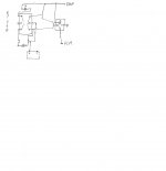
Here is my initial stab at wiring for both the torque converter and the EBPV through a DPST switch.
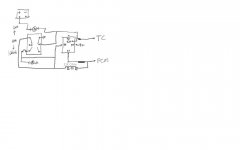


Bigger picture.

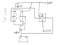
I have two modes that I call stock and tow. In tow mode I want everything controlled by the accelerator pedal. When I lift off the pedal, I want the torque converter to stay locked, even when the brakes are applied, and the EBPV to close automatically and stay that way until I either stop or step on the pedal again.

The torque convert lock up is achieved by interrupting the brake light signal to the PCM. The only other thing this affects, that I can find, is the cruise control disengagement. The cruise will still disengage by using the button on the steering wheel or by pushing the brake pedal hard enough to activate the back up disengagement pressure switch.

There are a couple issues with this approach as it sits with regards to cruise control function. It should work fine without cruise though. I think I was going to work on a way to use the back up disengagement pressure switch circuit to disengage the cruise easier. It also doesn't recognize the difference between letting off the pedal to slow down or letting off the pedal because the cruise control took over. I also don't have the resistor in the EBPV circuit to drop the voltage. Nothing more relays won't cure!

Anyway, I hope it helps.

Shawn
 

jschildm

Member
Joined
Jul 26, 2011
Messages
351
Reaction score
3
Location
Southeast Iowa
I will be using two seperate switches, operating independently of each other. One will control the EBVP (either Closed, PCM controlled, or Open) The main reason I wanted this was to keep it open during the winter when i dont want it opening and closing all the time. I figured while I was at it I may as well be able to use it for braking, and try to keep normal function while I was at it. The circuit for that would be the 3rd one posted (a corrected version - i think - of the first).

The second switch will be the TC control switch, again, operating independently of the other switch. I would like to have three availabe positions for it as well (locked, pcm controlled, and unlocked). The diagram for this is the second one posted.

Both switches are DPDT switches. I won't have anything near as fancy as your set-up would have. It would basically either be what the PCM commands, or manual control of both; on seperate switches. I am not sure either diagram will actually work. I have ran through it in my head and it makes sense to me (which means nothing, haha).

I actually finished wiring up the EBPV switch last night, and it seemed to function (at least the manual part). I didnt actually drive it around, but I should find out tomorrow if its working as it should or not.
 

jschildm

Member
Joined
Jul 26, 2011
Messages
351
Reaction score
3
Location
Southeast Iowa
Drove the truck today and everything seemed to function like I expected. It wasn't quite cold enough for the pcm to close the ebpv, but did come on right after firing it up.

I haven't done the TC switch yet, I need a resistor and wanted to make sure my other wiring diagram worked before I started messing with something a lot more expensive.

AZ Shang - I haven't had a chance to sit down and look at your diagram yet, but it sounds very useful. If I think of anything that might help you out I will leg you know. Thanks for the info, by the way.
 

AZStang

Member
Joined
May 19, 2011
Messages
95
Reaction score
0
Location
Tucson
Good deal, glad you got it to work. My only fear with manual lock up of the TC would be if you forget that it's locked or you lock it up too soon.

Shawn
 

Latest posts

Members online

Top