Blowby
Active member
- Joined
- May 22, 2011
- Messages
- 1,531
- Reaction score
- 0
Well I thought I would spend the day documenting an installation of the atmosphere turbo. Keep in mind that this is my take on the procedure and I'm sure there are better, faster or simpler methods to this process. With that said please post if you have shortcuts or a simple step to eliminate a few of mine. I encourage interaction from the 6.4 pro's out there.
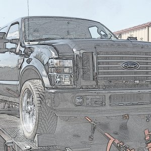
To keep this short and to the point I will not discuss removal of the air intake system since everyone probably has different ones. This is the engine bay of a 2009 F350 ready to start the job.

Make sure you get the Turbo Install Kit from your local dealer or any sponsor that has access to it - P/N 8C3Z-9T514-C. It will include everything needed including new bolts to replace the frikin studs that you will fight with while removing the up-pipes from the manifolds.
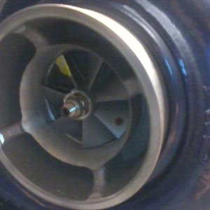
First thing I noticed was missing bolts holding the top of the turbine housings together. After I did a little research I was told they don't come from the factory with any. I did end up using this feature upon installation and I will cover that later.
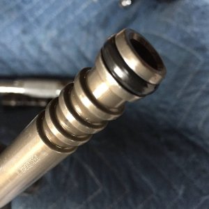
Remove the oil feed tube assembly from the top of the turbo center section. New washers will be included so make sure you remove any that are stuck to either side.

The lower connection is press fit. First remove the hold down bolt then pry it to achieve a straight up motion. I just used the hold down plate cocked at an angle to bind and lift the assembly.

Remove the down pipe clamp and you will notice a tab and a copper gasket (gasket not included in kit). Please keep the gasket for later use.

Pry up on the tab and push the pipe back and away from the turbo.

Now remove the bolts that clamp "Both" turbos in place over the oil drain system. Use a 1/2 breaker bar to make the job easier and a 15mm socket.


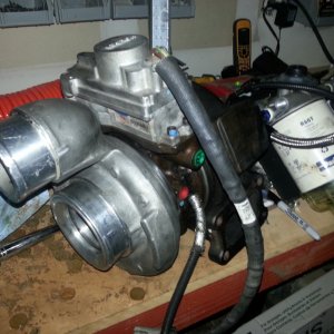
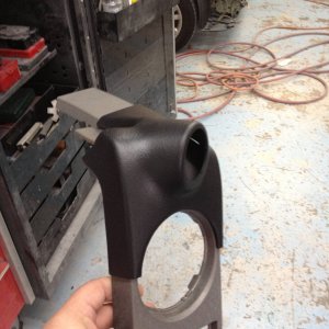
Remove the 4 nuts with a 13mm 1/4 socket to get into the space next to the hose. I removed 1 nut to release the dip stick tube first and a second nut underneath. This is the mounting bracket for the air charge from the atmo to HP turbos with other item on top.


You can see I pushed the dipstick down for clearance to access the last bolt. Also my 1/4 drive is in the center with room to work.

Look at the location of the stud after I removed the nut on the front in the middle of the first picture and on the back side in the second pic.


Now you can pry the bracket away from the center of the engine which will pop off the two turbos with a rubber seal in place.

Separation for the air charge between turbos. You can see the pry bar's black handle in the middle for location reference.

Now the fun part!
Removing the up-pipes at the exhaust manifolds. The best thisn to do is remove both wheel well covers. You can see I just let the cover rest on my tire. Access to the bolts and studs is much easier coming from the side. Spray with PB Blaster the night before.

On the passengers side I can remove the two to the right from the side. The one towards the center took a 13mm socket to break it loose. Remove nuts and spray with PB. Head to the other side and do the same.
Head back to the passenger side and with a 5mm 6 point socket remove the studs. Break loose or any sound or movement, spray then tighten the same amount. Repeat this and it will wick the PB Blaster into the threads. I had to use an extension of 1/4 to a knuckle to a 3/8 to be able to stay on the stud straight and apply a steady even force with the on/off technique.

Drivers side is a bitch. From the bottom the two center nuts and studs were not a problem accessing but the top was difficult. I used a 5mm 6 point, a knuckle and the driver. Worked perfect for the room available.

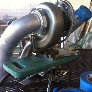
Removing the actuator nut. "Do Not" try to remove the nut without supporting the actuator arm on the VGT housing. This will put undue pressure on the arm controlling it. I used a socket that was long enough to stop movement before the any pressure was applied the the electronic device.

That's it for tonight! I'll finish the write up tomorrow. I'll ask the mod's to merge my posts when I'm done. If you want to comment or beat me up, go ahead.
:swordfight:
To keep this short and to the point I will not discuss removal of the air intake system since everyone probably has different ones. This is the engine bay of a 2009 F350 ready to start the job.
Make sure you get the Turbo Install Kit from your local dealer or any sponsor that has access to it - P/N 8C3Z-9T514-C. It will include everything needed including new bolts to replace the frikin studs that you will fight with while removing the up-pipes from the manifolds.
First thing I noticed was missing bolts holding the top of the turbine housings together. After I did a little research I was told they don't come from the factory with any. I did end up using this feature upon installation and I will cover that later.
Remove the oil feed tube assembly from the top of the turbo center section. New washers will be included so make sure you remove any that are stuck to either side.
The lower connection is press fit. First remove the hold down bolt then pry it to achieve a straight up motion. I just used the hold down plate cocked at an angle to bind and lift the assembly.
Remove the down pipe clamp and you will notice a tab and a copper gasket (gasket not included in kit). Please keep the gasket for later use.
Pry up on the tab and push the pipe back and away from the turbo.
Now remove the bolts that clamp "Both" turbos in place over the oil drain system. Use a 1/2 breaker bar to make the job easier and a 15mm socket.
Remove the 4 nuts with a 13mm 1/4 socket to get into the space next to the hose. I removed 1 nut to release the dip stick tube first and a second nut underneath. This is the mounting bracket for the air charge from the atmo to HP turbos with other item on top.
You can see I pushed the dipstick down for clearance to access the last bolt. Also my 1/4 drive is in the center with room to work.
Look at the location of the stud after I removed the nut on the front in the middle of the first picture and on the back side in the second pic.
Now you can pry the bracket away from the center of the engine which will pop off the two turbos with a rubber seal in place.
Separation for the air charge between turbos. You can see the pry bar's black handle in the middle for location reference.
Now the fun part!
Removing the up-pipes at the exhaust manifolds. The best thisn to do is remove both wheel well covers. You can see I just let the cover rest on my tire. Access to the bolts and studs is much easier coming from the side. Spray with PB Blaster the night before.
On the passengers side I can remove the two to the right from the side. The one towards the center took a 13mm socket to break it loose. Remove nuts and spray with PB. Head to the other side and do the same.
Head back to the passenger side and with a 5mm 6 point socket remove the studs. Break loose or any sound or movement, spray then tighten the same amount. Repeat this and it will wick the PB Blaster into the threads. I had to use an extension of 1/4 to a knuckle to a 3/8 to be able to stay on the stud straight and apply a steady even force with the on/off technique.
Drivers side is a bitch. From the bottom the two center nuts and studs were not a problem accessing but the top was difficult. I used a 5mm 6 point, a knuckle and the driver. Worked perfect for the room available.
Removing the actuator nut. "Do Not" try to remove the nut without supporting the actuator arm on the VGT housing. This will put undue pressure on the arm controlling it. I used a socket that was long enough to stop movement before the any pressure was applied the the electronic device.
That's it for tonight! I'll finish the write up tomorrow. I'll ask the mod's to merge my posts when I'm done. If you want to comment or beat me up, go ahead.
:swordfight: