My tow pig/DD build thread. F350/Cummins 6.7/twins/6R140

me2

New member
Joined
Nov 14, 2011
Messages
548
Reaction score
0
I'm glad to hear you guys are liking the build write up. Thanks for the feedback.
 

me2

New member
Joined
Nov 14, 2011
Messages
548
Reaction score
0
Swap Tactics

or

"Why isn't anything happening ?"

I have a philosophy about doing a swap. I don't touch anything on the recipient truck until I have as much figured out as possible and some sort of a plan to deal with everything. Put another way, there isn't any use yanking the engine and transmission out of the truck until I have all my ducks in a row for making it run.

So right now I'm still driving my 08 F350 daily. Its completely stock. I haven't touched a thing on it.

And every day I am tackling some aspect of the swap. Taking measurements, figuring out wiring, ordering parts, making notes, designing things, etc.

I keep a list and every time I come across something I don't know about the swap, I add it to the list. And every time I figure something out, I document it and cross it off the list.

I know its time to yank the engine and actually do the swap when I can't think of anything more to ask questions about and I have answers and parts and designs to everything on my list.

When is this going to happen ? I'm not sure. Hopefully in the next couple weeks. It depends on when I get all my questions answered, all the parts I need to do the swap and I run out of questions to ask.

Is everything going to go as planned once the engine is pulled ? Absolutely not.

But it will be one heck of a lot easier than if I start answering questions after the engine is pulled. Making up solutions on the fly to get the truck running again without enough forethought is not an efficient way (for me) to operate.

I made these tactics up when I did the swap in my '99. It was a simpler swap and I still spent a couple months gathering parts, wiring information, measurements and confidence before I pulled the engine. 10 days later, I had a running truck and I haven't really touched it since. It went very well.

One other thing I learned from my '99 swap is that once its done, you don't really want to go back and redo things. For example, the engine mounts aren't great on my '99 swap. I always said I was going to redo them, but I never have. So in some ways its better to do things right the first time rather than plan to go back and redo them later.

I'm hoping for the same outcome with this swap, but due to the transmission and the truck its going into, there are a lot more details to attend to. And I'll be taking baby steps with the engine and transmission as I go. They aren't going to do everything I want from them all at once.

So where exactly am I on the 08 swap ?

I have a lot of things mostly figured out. A lot of this I have not yet mentioned in this thread. I'll do that as I go along.

I'm still waiting for a few essential parts that should arrive here this week. And some decisions need to be made once those parts arrive.

I need to get a bit more detail on quite a few things. I have a lot of questions answered at the 75% level, but not the 100% level. 75% = this needs to connect to this. 80% = I need 2 hoseclamps and a 24 inch piece of hose to connect these two things. 100% = I have the parts in hand, ready to install.

And I need to look into a few concerns that have popped up recently, namely engine clearance in the engine compartment.

So its going to be a while until you see an engine pulled in this thread. But if I write up the stuff that IS going on, you'll see what goes into planning my swap when it does happen.

In the near future, I hope to see the following happen.

- engine teardown, rods replaced, head frost plugs replaced, studs installed, reassembly and paint
- mock up the twin turbo setup. I'll finalize it once the engine is installed
- install the battery boxes on the frame and get power cables started for the 6.7 installation
- install a dual filter fuel filtering setup. Check the capacity of the 6.4 low pressure fuel pump
- perform extensive CAN message logging and deciphering on the F350 for all of the transmission control input output PIDs
- perform some CAN message logging and deciphering on an 08 Dodge for a few essential Engine PIDs.
- finish data logging transmission shift info from a 2011 F350
- test installation of the transmission controller into the F350, talking with the chassis on the CAN bus
- install the engine wiring harness on the 6.7 and power it up
- test communication of the transmission controller with the 6.7 CAN bus
- connect the transmission controller up to the 6R140. Test that it interfaces properly to all the solenoids and sensors
- test out the transfer case motor operation on the 6R140 TC.
- verify the flex plate and starter geometry and sent out the CAD drawings for the adapter plate and various pieces

That covers about 80% of the big stuff left to be done.

As far as time goes, I've blocked off most of the next month or so to work exclusively on this project.

Stay tuned, there is lots of fun ahead.
 
Last edited:

redpitbull44

New member
Joined
May 29, 2012
Messages
3
Reaction score
0
Just wanted to say keep up the good work. You are a big inspiration to me. The 6R140 is a transmission that I am very interested in, as is the conversion you are doing. As a matter of fact, I became a member here just now because I found your build thread last night while doing my own research.
 

redpitbull44

New member
Joined
May 29, 2012
Messages
3
Reaction score
0
Also, what is it that you do for a living, or rather, where did you learn the computer related things you know? I am a diesel mechanic, and embarrassed to say I learned things over the last 7 pages I feel should have been common knowledge to me.
 

me2

New member
Joined
Nov 14, 2011
Messages
548
Reaction score
0
Making It All Work

aka, "What is all this CAN stuff about ? I like my beer in bottles !"

The more electrical gadgets you add to a vehicle the more communication you need. Power windows can only go up when the key is on, the radio gets louder the faster the truck goes, etc. All that interelated "smart" functionality needs information from outside the component to make it work intelligently.

Historically, this was done with a separate wire for every function that needed to be communicated. With the outbreak of luxury vehicles loaded with "smart" gadgets, the wiring mess became too great and someone came up with the idea of transmitting the required information via messages on a network instead of using individual wires.

CAN Bus is that network. You can read more about it here, but Google is your friend if you need more or less info.
http://en.wikipedia.org/wiki/CAN_bus

The quick explanation is that CAN Bus is like an Ethernet network in your truck, only instead of your daughter video chatting with grandma, its your engine ECM telling the transmission TCM that its overloaded and needs to downshift the transmission.

Just to be clear, CAN is not interoperable with Ethernet in any fashion. Its just an analogy to make it easier to understand.

So what does this have to do with my swap ? I intend to make full use of the Ford CAN Bus to make everything work. BECAUSE I HATE WIRING !

Am I crazy ? I don't think so. Lets look at it in more detail. Lets consider how I am going to make the accelerator work with the 6.7.

Traditionally, there are several ways to wire an accelerator into a Cummins swap ECM.

1) use an engine mounted accelerator sender (APPS) and control it with an accelerator cable from a gasser. This was common with the 24V and early CR engines that used an engine mounted APPS.

2) Mount a Cummins APPS ( and the accelerator pedal assembly) in the truck cab and wire it into the 6.7 ECM.

3) Intercept the signal from the Ford APPS and convert it to the APPS voltages the Cummins ECM needs.

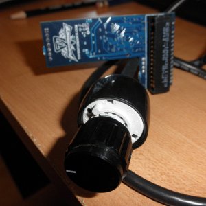
4) Read the signal from the Ford APPS with a microcontroller and have it generate a synthetic Cummins APPS signal.

FWIW, I started with #3 in my '99 swap and upgraded to #4. It works well.

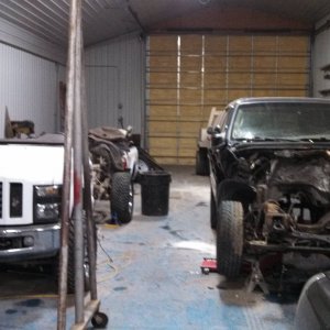
With my 08 swap I am going to do something completely different.

A stock 08 F350 has 2 CAN buses on it.

One, called the low speed CAN bus, is used to send trivial chassis type information around the vehicle. Things like air temperature, DVD status in the rear seat player, that sort of stuff.

The other bus is called the high speed bus and it sends all sorts of real time informational all over the truck. Engine temperature, engine load, cruise control status, etc.

It turns out that accelerator position is one of the pieces of data on the high speed bus. The stock Ford accelerator pedal is hard wired into the ECM. The ECM then provides accelerator pedal information to any device that needs it in the form of a message on the CAN Bus.

What module would ever need to know the accelerator pedal information other than the ECM ? Well, the transmission control unit for one. And the ABS controller module. And probably the air bag controller module.

So instead of having several wires (because APPS units provide multiple signals to be failsafe) to every module that needs its information, the ECM handles reading the APPS and sends the data on the 2 wire CAN network to wherever its needed.

So what does this have to do with the 6.7 throttle signal ? Well, instead of hard wiring an APPS into the 6.7 ECM, I am going to read the throttle position message on the Ford high speed CAN bus with a micro controller and then generate a synthetic APPS signal for the Cummins ECM to use.

Now why would you want to do that ? An APPS is only 4 wires.

For a couple reasons.

1) I don't have to touch any of the stock Ford APPS wiring. Which means a) less work, b) no holes for new wires in the firewall, c) troubleshooting my truck is the same as a stock truck, including the wiring diagrams in the shop manual and checking the status of the APPS (on both the Ford ECM and the Cummins ECM!) via a scan tool, etc.

2) There is no cost, other than the micro controller, which is needed anyway, as we'll see. I don't have to buy a Dodge APPS, for example.

3) The Ford ECM still receives a proper APPS signal. Which means that it still sends a proper APPS message to all the modules that need it, such as the ABS module and the transmission control module.

And whatever else might need it that we don't know about and don't care to have to learn about.

4) I can now use the APPS message anywhere that I need it, for example in the transmission controller for the 6R140.

If I didn't use a CAN message to get that information, not only would I have to wire the APPS signal into the 6.7 ECM, I'd also have to wire it into the 6R140 TCM.

5) It allows me to have full control over the APPS signal that the 6.7 ECM receives.

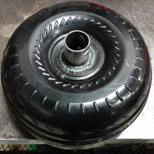
Remember how I'm hoping my engine will make 1200 ftbls. And remember how the 6R140 torque converter has a torque ratio of 1.8 and an input shaft rating of 1400 ftbls ?

If I want the stock 6R140 to live, I need to dial down the power from the engine anytime the TC is unlocked. 1.8 x 1200 = 2160 ftlbs, which is 50% more than the 6R140 is rated to handle. But if the TC is locked, 1200 ftlbs is less than the 1400 ftlbs it can handle.

** I'm assuming the 6R140 is incapable of handling more torque than its stock rating, which has been proven otherwise in practice. I'm doing this for an example, but in practice I'll probably have a tow setting on the TCM that does limit the engine power when the TC is unlocked. When you make your own TCM, you can do that.**

I can easily dial down the power on the 6.7 by dropping the throttle signal the micro controller generates and if the micro controller knows when the TC is unlocked (via another CAN bus message, of course !) then I can cut the engine back until its safe.

It would be pretty hard to do that without CAN bus messages.

Lets do another example.

The Smart Junction Box in an 08 F350 needs to know that the engine is running at 500 RPM or faster before it will turn certain things like air conditioning on. Thus we need a tach signal.

But do we ? The SJB doesn't have an input from the engine for a tach signal. It gets its information from a CAN message.

Where does that CAN message come from ? The Ford ECM.

So one thing we could do is wire up a couple dummy crank and camshaft sensors on the 6.7 to simulate the 6.4 tach signals and feed them to the Ford ECM. This would allow the Ford ECM to see the crank and cam signals from which it will then send out an engine speed message on the CAN bus and wala, the SJB is happy and we have air conditioning.

My wife and kids like AC when its hot out.

However, there is an even better way. It turns out the Cummins ECM has its own CAN bus, albeit a different language than the Ford CAN bus. And the Cummins ECM has its own engine speed message. So "all" we have to do is read the Cummins engine speed message and send it on the Ford CAN bus where it will be received by the SJB and we will have working AC.

Again my wife is happy.

Isn't that a lot of work to just turn on the AC ? Some might think so, but it turns out that the tach in the dash also needs the engine speed message on the CAN bus. When we read the Cummins message and send a Ford message, we also get a working tachometer. And the transmission controller also needs to know how fast the engine is running so that it can calculate how much slip is occuring across the torque converter, amoung other things. CAN Bus data is very pervasive. Its used in places you would never expect until you think about it for a while.

And again, there are wiring savings and cost savings and its easier to troubleshoot and the list goes on.

At some point in the future I am going to wire a 1000 watt pure sine inverter into the cab of my truck with several outlets so that everyone can plug in their AC gizmos and be happy.

And guess what ? I don't want that inverter to run unless the engine is running because it will draw about 100 amps and kill the batteries very quickly.

So I'll make my own little smart junction box and have it watch for the engine RPM message on the CAN bus and turn the inverter on and off as necesary.

Because if I don't build that intelligence into my truck, some night I'll shut the engine off with the inverter still running and the next morning my batteries will be dead.

And all it takes is 2 wires and a little software to make that magic happen.

Thus far I have used 2 simple examples, the throttle signal and the engine speed signal. But I intend to control just about everything installed on my truck with the CAN Bus, one way or another. Air conditioning, transfer case shifting, dash gauges, accessory gauges, transmission controller, cruise control, etc, are all connected to the CAN Bus in one way or another.

And with a bit of work I think I can make them function like they would if the Cummins 6.7 was installed in my truck from the factory. Try doing that with conventional wiring techniques.

I'm about waist deep into this CAN stuff right now. I can see its potential. I understand all the theory and I'm watching data on various buses. I'm just about to start injecting my own data onto both Ford and Cummins buses.

Using the CAN Bus fopr integrating everything is by no means a sure thing, but if it works it will dramatically simplify the wiring of my engine swap and make it much more factory like.

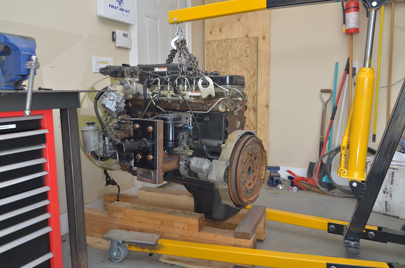
I'm off to get my hands dirty on an engine.
 
Last edited:

me2

New member
Joined
Nov 14, 2011
Messages
548
Reaction score
0
Also, what is it that you do for a living, or rather, where did you learn the computer related things you know? I am a diesel mechanic, and embarrassed to say I learned things over the last 7 pages I feel should have been common knowledge to me.

I am very happy you got something out of it, because often I feel like a fool typing out stuff that I wonder if only I didn't know !

I knew nothing about EFI Live, Ford CAN bus, the 6R140, and even the Cummins 6.7 when I started out in November. Don't believe me ? Go search some of my automatic transmission posts on Powerstroke Nation from last fall. Hillarious.

Lets be honest, the success of this whole swap is still a long way from a sure thing. I am WAY out on a limb with a lot of this stuff. But I keep pecking away at things and learning and putting 2 and 2 together and it looks like there is a possibility it will work.

Some big tests are on the horizon...
 
Last edited:

me2

New member
Joined
Nov 14, 2011
Messages
548
Reaction score
0
In case I've driven some of you to roll your eyes over and paint this swap as hopeless, not everything I'm proposing is new to me.

Except the 6R140 controller. That will be completely new to me. Luckily it has a mechanical limp mode ! LOL LOL LOL

Here is the circuit that ran the throttle on my '99 swap for the first 3 years of its existence.

DSC_7034.jpg


It converts the 0.8 to 4 volts(?) from a Ford APPS (TPS in Ford land) to the 05 Cummins ECM throttle input voltages. It totally ignores the idle validation switch !

It worked well but didn't like car washes and didn't handle cruise control or AC.

I built this circuit because when my 05 CR arrived I found it didn't have an APPS like the other CRs I had seen and the engine mounted APPS units were expensive and on back order at the time.

And nobody could tell me if the output from an 03.5 APPS would work with the 05 CR. As a matter of fact, I still don't really know.

Like I said, school of hard knocks.

This is the circuit that is running the throttle, cruise control and AC compressor on my current 5.9CR swap.

DSC_7037.jpg


This is a micro processor based solution. It took a day or so to make. All of the inputs and outputs are analog. I had to splice into several Ford wires to hook it up. It would have 1/3 the wires if it was getting its inputs and controlling things via the CAN Bus.

So the big difference between what I've done in the past and what I want to do with my 08, is that instead of hard wiring stuff into the controller, I want to read and write CAN messages. Which I think will make things dramatically easier.

If everything went perfectly, the only wires I'd have to touch on the truck itself would be connections to the CAN Bus.

We'll see how things play out as we go forward.

Edit. Correction a couple posts above, a Cummins APPS is 6 wires, not 4.
 
Last edited:

Hotrodtractor

Moderator
Joined
May 18, 2011
Messages
4,934
Reaction score
14
Location
Mingo, Ohio
So have you actually been able to locate an accurate list of the Cummins specific CANbus based IDs and data descriptions - or do you intend on sniffing all of them out and deciphering them?

Honestly that is something I have wanted to try, but just have never taken the time - although I think I have all the equipment necessary to begin taking the look with some freeware. Any additional details to your experience with reading and interpreting both the standard CANbus and the specialized CANbus protocol that Cummins uses would be greatly appreciated.

Jason
 

me2

New member
Joined
Nov 14, 2011
Messages
548
Reaction score
0
So have you actually been able to locate an accurate list of the Cummins specific CANbus based IDs and data descriptions - or do you intend on sniffing all of them out and deciphering them?
Some of the messages are J1939 format. Others are proprietary. I've never been able to find anyone who will share the list, but I know people who have it.

The SAE J1939-71 document is the latest revision to the standard.

Honestly that is something I have wanted to try, but just have never taken the time - although I think I have all the equipment necessary to begin taking the look with some freeware. Any additional details to your experience with reading and interpreting both the standard CANbus and the specialized CANbus protocol that Cummins uses would be greatly appreciated.
All I can say is jump in.
 
Last edited:

Mark Kovalsky

Active member
Joined
Jul 11, 2011
Messages
1,181
Reaction score
4
Location
SE Florida, USA
** I'm assuming the 6R140 is incapable of handling more torque than its stock rating, which has been proven otherwise in practice.

As you stated the 6R140 is rated at 1400 lb-ft after the torque converter. This rating was certified by testing and calculation, but it is not an absolute limit. It is the torque level that the trans was designed to live with for it's design life. If you go above 1400 lb-ft you most likely won't immediately break parts, but parts will start to fatigue at a higher rate, shortening the transmission's life.
 

me2

New member
Joined
Nov 14, 2011
Messages
548
Reaction score
0
As you stated the 6R140 is rated at 1400 lb-ft after the torque converter. This rating was certified by testing and calculation, but it is not an absolute limit. It is the torque level that the trans was designed to live with for it's design life. If you go above 1400 lb-ft you most likely won't immediately break parts, but parts will start to fatigue at a higher rate, shortening the transmission's life.

Music to my ears, Mark. Thanks for clarifying.

What is the design life on a transmission like the 6R140 ?
 

me2

New member
Joined
Nov 14, 2011
Messages
548
Reaction score
0
Mounting the engine stand adapter to the engine.
DSC_7044.jpg


DSC_7048.jpg


Lift off, with the fully assembled engine crane. This is the first time the engine has moved in 7 months.

DSC_7054.JPG


Transfering the engine from the crane to the stand. This went way better than I ever dreamed, thanks to the crane fitting underneath the stand the the good wheels I put on everything.

I easily tranfered the engine from the crane to the stand all by myself.

Notice the bent lifting arm on the crane. I'll be replacing it with something heavier.

This crane replaced an older non folding crane that I sold. Almost everything on the old crane was heavier than on the new crane.

DSC_7055.jpg


Engine mounted on the engine stand.

DSC_7063.jpg


Its very stable in the stand, though the center post does flex a bit.

I love the height of the engine. Its perfect for working on.

This is the floor stand that I built to hold it. I think its 12.5" between the 2x4s and the raised up section is 24 inches long. If you don't need to work on the underside of the engine, a stand like this works fine.

Though its a pain working on the floor.

The pock marks on the raised 2x4s are from the pan bolts.

DSC_7058.jpg


First up was removing the fan. Contrary to Internet opinion, it DOES NOT have a left handed thread !

fan%2520drive%2520nut%2520removal%2520instructions.jpg


I used a small C clamp to hold the pulley. A couple hammer whacks on an el cheapo imported 36 mm wrench got it off easily.

DSC_7067.jpg


The teardown continues.
 
Last edited:

bad12jr

New member
Joined
May 25, 2011
Messages
1,244
Reaction score
0
Amazing info. What are you using to read and write can bus messages. I'm slowing working on getting some info together for a 06 CR swap into an 05 to 07 f350. A garage to do it in is first in the order as you probably know.


Sent from my x2 somewhere
 
Last edited:

Latest posts

Members online

Top