PMF OBS Dana 60 Dual Steering Stabilizer Kit

JSchuricht

Member
Joined
Apr 14, 2012
Messages
159
Reaction score
1
Location
AZ
Bump for some updates. I have a heck of a lot more faith in you than asic bitcoin miner preorders but it's still nice to see some progress once in a while.
 

NotStock

New member
Joined
May 23, 2011
Messages
1,274
Reaction score
0
Location
Tucson, AZ
My apologies, it has been busy around here. Here is a pic of the stabilizers mounted in the lower position which would be for low lift amounts. Im adding 1/4" more clearance to allow the stabilizers to flip to the top side for higher lift amounts. There wasnt quite enough clearance on the draglink.
 

Attachments

  • 20150106_172629.jpg
    20150106_172629.jpg
    319.6 KB · Views: 144

JSchuricht

Member
Joined
Apr 14, 2012
Messages
159
Reaction score
1
Location
AZ
It arrived!

Guessing on how assembly will go, too cold and wet to get under the truck right now.

sP1020919.jpg

sP1020920.jpg

sP1020921.jpg
 

GO BIG OR GO HOME

New member
Joined
Jun 21, 2011
Messages
825
Reaction score
1
Location
Graham, NC
That looks amazing. I'm sure mine has been delivered by now but I'm in Texas working so I'll just drool over yours for now

Sent while doing burnouts somewhere in the country
 

NotStock

New member
Joined
May 23, 2011
Messages
1,274
Reaction score
0
Location
Tucson, AZ
Outer brackets flip opposite of what they are in your pictures. Shocks can mount on either the bottom or the top side of the middle bracket depending on what size of lift you have. The higher the better as it will avoid road debris more.
 

JSchuricht

Member
Joined
Apr 14, 2012
Messages
159
Reaction score
1
Location
AZ
Well, I have some bad news. There are clearance issues on several parts. For reference, this is a 95 F-250 with a 93 Dana 60 on a Sky RSK with SD springs and a drop pitman arm. All steering components are Moog and were purchased mid 2012.

On the passenger side if the bracket is held parallel to the round, it hits the drag link. This may just be a positioning issue, looking at the pics perhaps the bracket needs to be mounted more toward the center but that still doesn't account for the other issues.
sP1020923.jpg


With the shock in the upper mount position, the boot rubs the drag link. I think the fix could be having one bracket 1/2" longer than the other.
sP1020926.jpg

sP1020929.jpg

sP1020930.jpg


Then there's the main mount. It sits extremely close to the tie rod with the wheels straight ahead but turning the wheels results in binding long before full lock. Perhaps dropping the center section 1/2" or creating a bend would fix it. On the plus side, it does mount up to a Crane cover.
sP1020933.jpg

sP1020934.jpg
 
Last edited:

NotStock

New member
Joined
May 23, 2011
Messages
1,274
Reaction score
0
Location
Tucson, AZ
John, I just left you a message. Call me back when you get a chance and we can go over how you have everything mounted. The kit we installed had more clearance than what you have and we even added a little more for variance between vehicles. The outer mount needs to be moved toward the center of the truck as well.
 

Tom S

Moderator
Joined
May 20, 2011
Messages
3,365
Reaction score
1
Did you get it worked out? Still want one of these for my truck.
 

JSchuricht

Member
Joined
Apr 14, 2012
Messages
159
Reaction score
1
Location
AZ
Trevor has a new version with a bit more clearance that he is sending me. I will post some pics as soon as it shows up.
 

JSchuricht

Member
Joined
Apr 14, 2012
Messages
159
Reaction score
1
Location
AZ
I took a few pics before shipping the old parts back.

Here are the brackets that clamp on the tierod. The new ones are about 1/4" longer. They also have shorter bushings presumably to help keep the shocks level with the new center bracket.
sP1020957.jpg


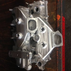
New center bracket on right, old on left.
sP1020958.jpg


Top down view of the old center bracket.
sP1020959.jpg


Top down view of the new center bracket, notice the gap difference.
sP1020960.jpg


Much more clearance.
sP1020962.jpg


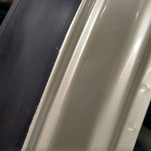
With a Crane cover, the driver side bracket was just touching at full lock so the corner had to be ground down slightly.
sP1020965.jpg


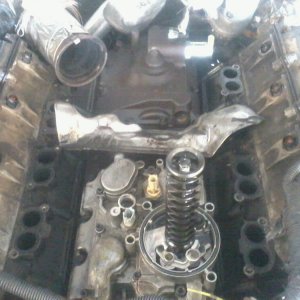
Ran into one new issue, likely from using bolts from the original brackets with new brackets. The bolts are way too long.
sP1020967.jpg


Fortunately I had some thick washers laying around.
sP1020966.jpg


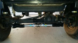
Random picture of the center before tightening everything down.
sP1020968.jpg


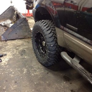
The sun was not at a good angle but here's a pic of everything installed. There is a larger pic behind this one if you click on it.
sP1020969.jpg
 

NotStock

New member
Joined
May 23, 2011
Messages
1,274
Reaction score
0
Location
Tucson, AZ
I'm glad V3 passed your exacting eye. I'm still intrigued by how different trucks can be. We work within 1/16" tolerence and yet the OEM's are regularly out 1/2" or more.
 

JSchuricht

Member
Joined
Apr 14, 2012
Messages
159
Reaction score
1
Location
AZ
I didn't realize you were up to version 3. I hope you don't take any of this personally Trevor. I know your reputation and I have a ton of faith in the work I have seen from you. I merely intend to post as much factual information as I can because that's what I love to see when I am looking for info on something and in reality, seeing you solve an issue vs chocking it up to a customer issue like a lot of manufactures do goes a long way. In my line of work, everything is measure in angstroms and nanometers so I tend to look for the small stuff. If anything, I hope you take it as constructive criticism.

One thing I had been wanting to test but ran out of time is deflection of the axle. I wanted to put a dial on the axle and see how much it has deflected in relation to the pumpkin when jacked from the center as I had done. I didn't need the clearance to get under the truck, but it makes it much easier to turn the wheels wile underneath to check for binding. That may have had some effect on the tolerances that caused issues.

I am also amazed by the difference between trucks. The knuckles are cast so there should be minimal difference between units, my best guess is in the mounting of the C's and the milling of the knuckles after casting. This was a 93 axle so it was likely done with jigs that wear over time vs a modern computer aided system that can correct for variations.

Out of curiosity, do you cut these out on a waterjet? It would be great to seem some shots of your equipment in action. I'm a geek and seeing how stuff works is practically porn to me.
 

NotStock

New member
Joined
May 23, 2011
Messages
1,274
Reaction score
0
Location
Tucson, AZ
We released the second version which was what you first received. There is always going to be slight variations and if there is any way we can change a product to make it work better, fit better or anything else, we will do so. All of our parts are laser cut inhouse with a 3.2 KW laser. Waterjet is too slow and expensive for the materials we run. If we were running super thick stuff or non metallics, that would be the way to go. We have considered getting a small one just to do flanges and such with.
 

Members online

No members online now.
Top