ja_cain
Active member
- Joined
- Aug 10, 2013
- Messages
- 4,597
- Reaction score
- 2
I know. And the bench is super expensive....
Sent from my iPhone using Tapatalk
My buddy built one for a fraction of the cost. I'll see if I can dig up a video of it.

I know. And the bench is super expensive....
Sent from my iPhone using Tapatalk
Piezo's are crazy fast. Fast enough to have multiple injection pulses per compression event.
I thought I had two of those labjacks at work, but could only find one. Ill look again on Monday when I'm at work. If I can find the non-pro model, I'd be willing to send it to you as long as you promise to follow through on this project.Let me know if you think you would like to use it and I will see if I can find the other one.
I think you need to keep CID and FDCS in the same routine. Those cannot be run in seperate routines and everything work out in my experience. They are tied at the hip.
You know the "off time" on the FDCS is in between injectors, and the injector pulsewidth is defined by the time that FDCS is high after the leading edge of each event right? You don't pick the low, you pick the high and the low is just what's left before the next injector at the rpm in question.
Building a flowbench, pulsewidth and shot count are the bible.
My buddy built one for a fraction of the cost. I'll see if I can dig up a video of it.
He doesn't have the video anymore, but will make another when he is off vacation. I'll post it up once he sends it to me.Lmk!
Sent from my iPhone using Tapatalk
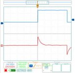
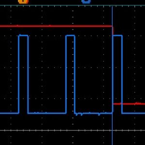
Take a look at the last image I posted. I expect to see two square waves from the PCM to the IDM for CID and FDCS, but instead of CID were getting what looks like IDM to injector signal. We double check the pins and wire from the PCM to IDM.